Introduction
Radioactivity is the spontaneous emission of radiations from unstable atomic nuclei. These radiations may be alpha particles, beta particles, gamma rays, or other nuclear emissions. Since radioactive radiations are invisible and can be harmful, they are detected using special instruments.
The choice of detector depends on the type of radiation, intensity, energy, dose rate, sensitivity required, and whether the aim is simple detection, dose measurement, or energy analysis.
Basic principle of radioactivity detection
Radioactive radiations interact with matter and produce measurable effects. Detection instruments convert these effects into visible tracks, electrical pulses, light flashes, darkening of film, or stored dose information.
| Detection effect | Used in |
|---|---|
| Ionization of gas | GM counter, ionization chamber, proportional counter |
| Light emission | Scintillation counter |
| Electron-hole pair formation | Semiconductor detector |
| Condensation track | Cloud chamber |
| Photographic darkening | Film badge |
| Thermoluminescence | TLD |
Different methods of detecting radioactivity
- Geiger-Muller counter
- Ionization chamber
- Proportional counter
- Scintillation counter
- Semiconductor detector
- Cloud chamber
- Photographic film badge
- Thermoluminescent dosimeter
1. Geiger-Muller counter
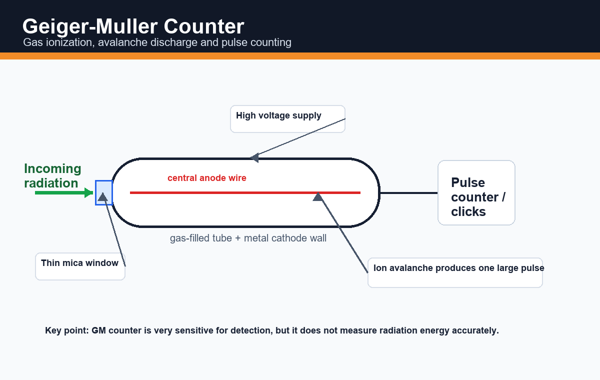
The Geiger-Muller counter, or GM counter, is a gas-filled detector used for detecting alpha, beta and gamma radiations. It is one of the most popular radiation detectors because it is simple, portable and sensitive.
Theory
The GM counter works on the principle of ionization of gas followed by avalanche discharge. When radiation enters the GM tube, it ionizes the gas inside the tube. The electrons produced move towards the central anode wire and positive ions move towards the cathode wall.
A high potential difference is applied between anode and cathode. The electrons gain enough energy to produce further ionization. This produces an avalanche of ions and a large electrical pulse. Each pulse is counted as one radiation event.
Construction
- GM tube: gas-filled detector tube.
- Cathode: metallic wall of the tube.
- Anode: thin central wire.
- Thin mica window: allows weakly penetrating alpha or beta particles to enter.
- Filling gas: inert gas such as argon, neon or helium.
- Quenching gas: halogen or organic vapor to stop continuous discharge.
- High voltage supply: creates strong electric field.
- Pulse counter: counts electrical pulses.
Working
- Radiation enters the tube through the window or wall.
- The gas is ionized.
- Electrons accelerate towards the anode.
- Secondary ionization produces an avalanche.
- A large pulse is produced.
- The pulse is counted and may produce a click sound.
Procedure
- Connect the GM tube with the counter and high voltage supply.
- Switch on the instrument and allow it to stabilize.
- Record background count for one minute without source.
- Place the radioactive source at a fixed distance from the GM tube window.
- Record counts for a fixed time.
- Repeat readings and take the average.
- Subtract background count from observed count.
Observation and calculation
Corrected count rate = observed count rate – background count rate
Background count is due to cosmic rays and natural radioactivity, so background correction is necessary.
Plateau and dead time
The plateau region is the operating voltage range where count rate remains nearly constant with small voltage changes. The dead time is the short time after one count during which the tube cannot detect another event.
Advantages
- Simple and portable.
- Highly sensitive for routine detection.
- Quick response with audible clicks.
- Useful for contamination monitoring and safety surveys.
Limitations
- Cannot measure radiation energy accurately.
- Cannot easily distinguish alpha, beta and gamma without absorbers or special design.
- Dead time causes counting loss at high count rate.
- Not suitable for precise spectroscopy.
2. Ionization chamber
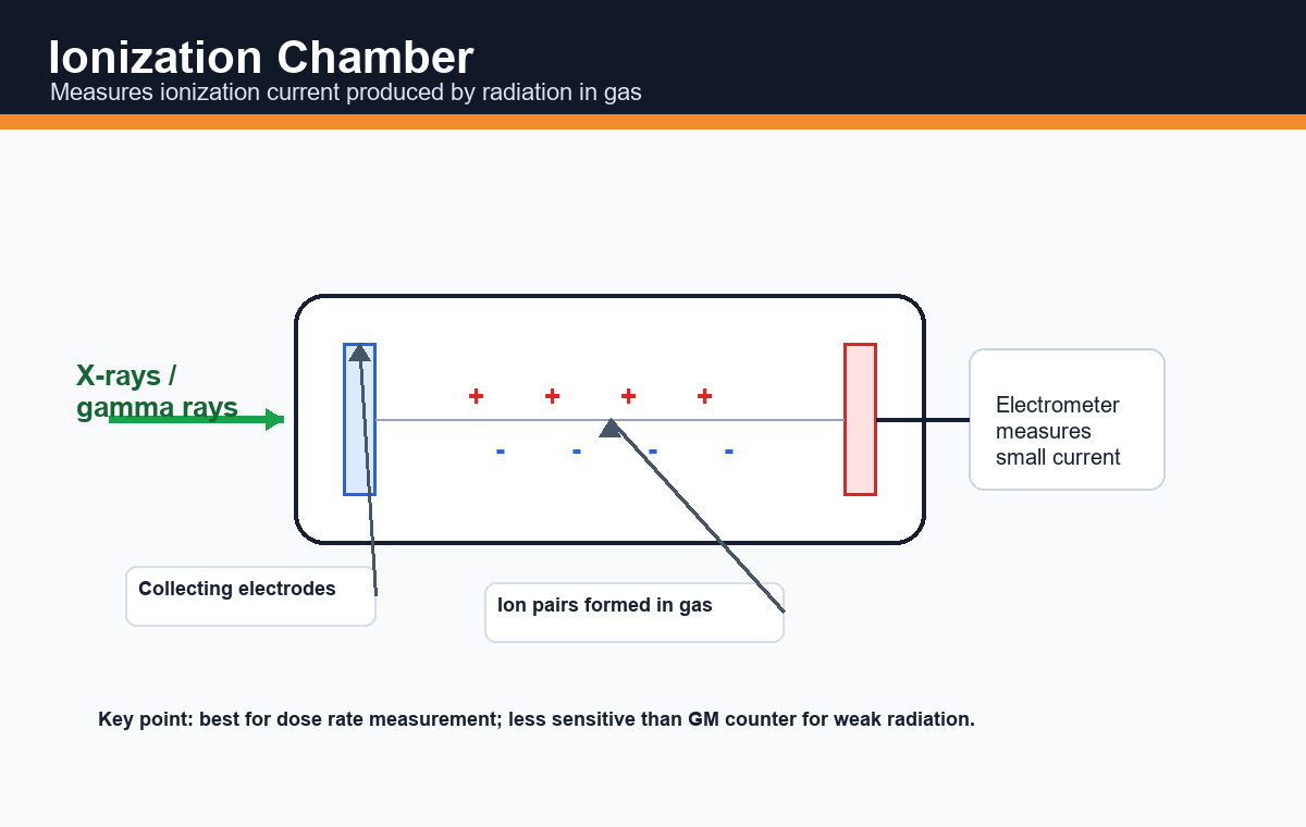
Theory
An ionization chamber is a gas-filled detector operated at relatively low voltage. Radiation ionizes the gas, and the produced ions are collected by electrodes to give a small ionization current.
Procedure
- Connect the chamber to an electrometer.
- Apply suitable voltage.
- Expose the chamber to radiation.
- Measure the ionization current.
- Relate current to dose rate or radiation intensity.
Uses
Ionization chambers are useful for dose rate measurement, radiation therapy dosimetry, X-ray monitoring and gamma radiation measurement.
3. Proportional counter
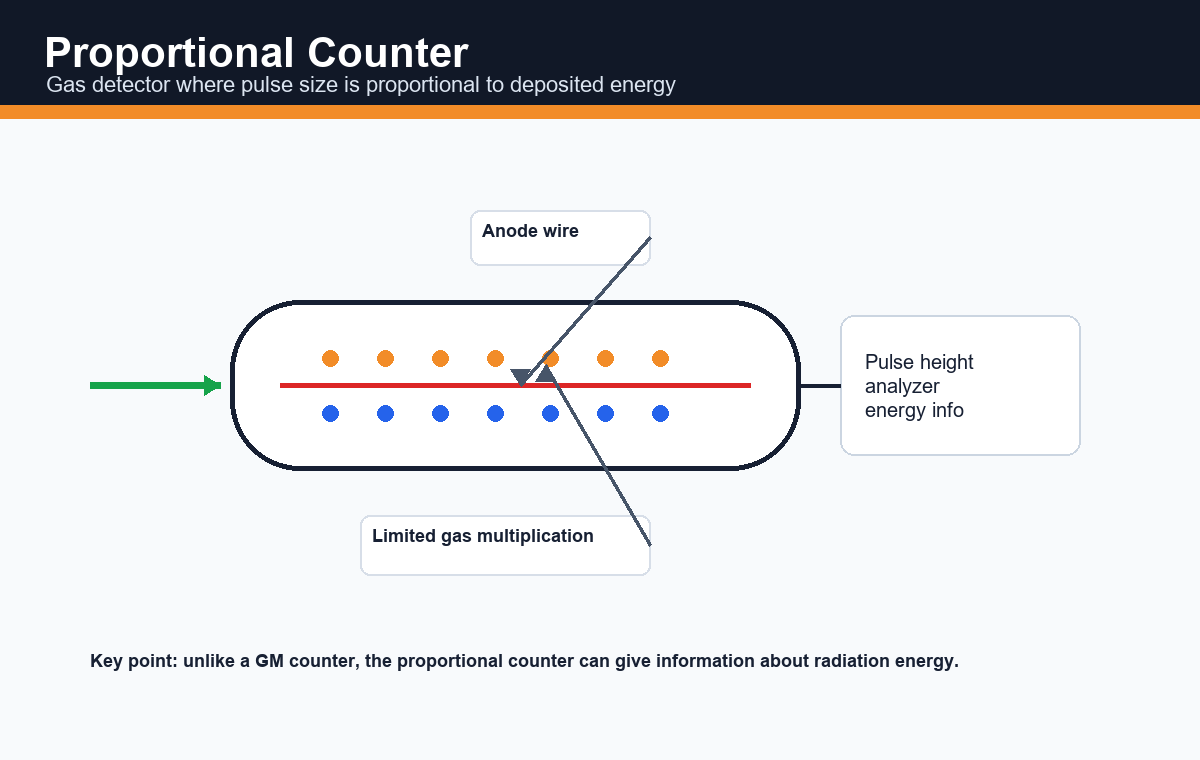
Theory
A proportional counter is operated at a voltage higher than an ionization chamber but lower than a GM counter. It produces gas multiplication, but the pulse height remains proportional to the energy deposited by the radiation.
Procedure
- Apply suitable proportional-region voltage.
- Allow radiation to enter the gas-filled tube.
- Collect pulses produced by limited gas multiplication.
- Analyze pulse height for energy information.
Uses
It is used for alpha and beta detection and where information about radiation energy is needed.
4. Scintillation counter
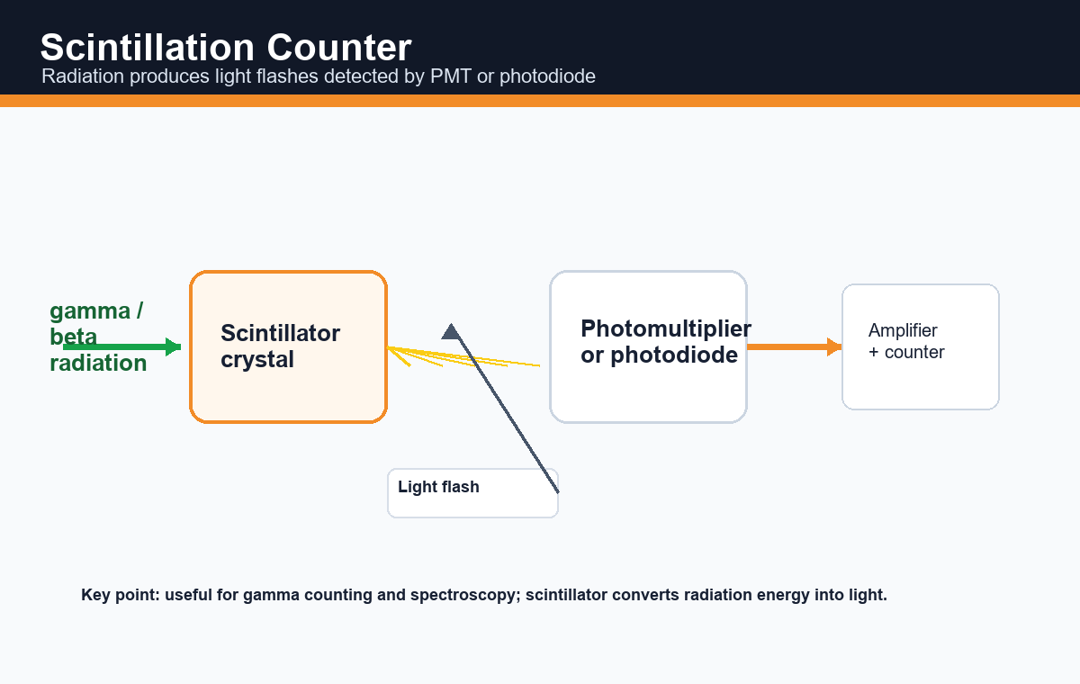
Theory
In a scintillation counter, radiation strikes a scintillator and produces tiny flashes of light. These flashes are detected by a photomultiplier tube or photodiode and converted into electrical pulses.
Procedure
- Select a suitable scintillator such as NaI(Tl) for gamma rays.
- Place the radioactive source near the detector.
- Radiation produces light flashes in the scintillator.
- The photodetector converts light into electrical pulses.
- The pulses are counted or analyzed for energy.
Uses
Scintillation counters are used in gamma counting, nuclear medicine, environmental monitoring and radiation spectroscopy.
5. Semiconductor detector
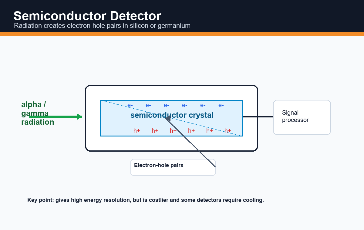
Theory
Semiconductor detectors use materials such as silicon or germanium. Radiation creates electron-hole pairs in the semiconductor crystal. These charges are collected and converted into electrical signals.
Procedure
- Apply bias voltage to the semiconductor detector.
- Allow radiation to enter the active region.
- Electron-hole pairs are formed.
- Collected charges produce a signal.
- Signal processing gives count or energy spectrum.
Uses
Semiconductor detectors are used for high-resolution alpha, beta, X-ray and gamma spectroscopy.
6. Cloud chamber
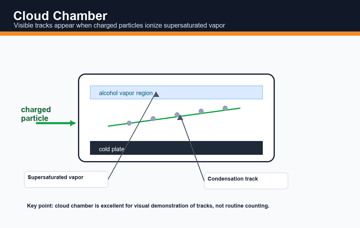
Theory
A cloud chamber contains supersaturated vapor. Charged particles ionize the vapor, and droplets condense along the ionized path, making a visible track.
Procedure
- Create a supersaturated vapor region.
- Cool the base plate.
- Allow radiation to pass through the chamber.
- Observe visible tracks formed by condensation droplets.
Uses
Cloud chambers are useful for demonstration of alpha and beta particle tracks and for visual understanding of radiation paths.
7. Photographic film badge
Theory
A photographic film badge works because radiation darkens photographic film. The amount and pattern of darkening indicate radiation exposure.
Procedure
- Radiation worker wears the film badge during work.
- Radiation passes through filters and exposes the film.
- The film is later developed.
- Darkening is compared with standards to estimate dose.
Uses
Film badges are used for personal radiation monitoring in laboratories, hospitals and nuclear facilities.
8. Thermoluminescent dosimeter
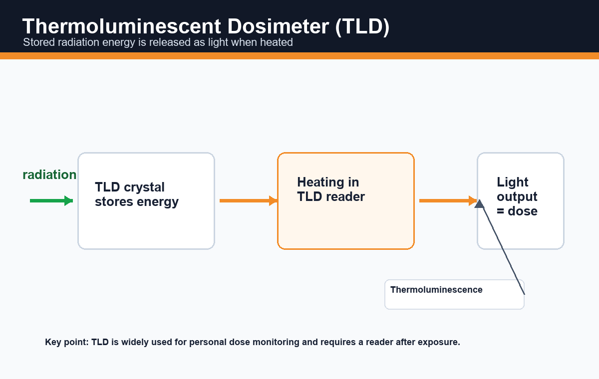
Theory
A thermoluminescent dosimeter, or TLD, stores energy from radiation in a crystal. When the crystal is heated in a reader, it emits light. The emitted light is proportional to the radiation dose.
Procedure
- Wear or place the TLD in the radiation field.
- The crystal stores energy during exposure.
- After exposure, heat the TLD in a reader.
- Measure the emitted light.
- Calculate the absorbed dose.
Uses
TLDs are widely used for personal dose monitoring, medical dosimetry and environmental radiation measurement.
Comparison of radioactivity detection methods
| Detector | Main principle | Best use | Main limitation |
|---|---|---|---|
| GM counter | Gas ionization and avalanche pulse | Routine detection | No accurate energy measurement |
| Ionization chamber | Ionization current | Dose rate measurement | Less sensitive for weak radiation |
| Proportional counter | Pulse proportional to deposited energy | Particle detection with energy information | Requires stable voltage operation |
| Scintillation counter | Radiation produces light flashes | Gamma counting and spectroscopy | Needs optical detector |
| Semiconductor detector | Electron-hole pair formation | High-resolution spectroscopy | Costly; may need cooling |
| Cloud chamber | Condensation tracks | Visual demonstration | Not routine quantitative counting |
| Film badge | Film darkening | Personal monitoring | No instant reading |
| TLD | Light emission on heating | Personal dose measurement | Needs reader after exposure |
Precautions while using radioactive sources
- Use radioactive sources only under supervision.
- Keep maximum possible distance from the source.
- Minimize exposure time.
- Use shielding when required.
- Do not touch radioactive sources directly.
- Store sources in labelled containers.
- Always record background count before measurement.
Summary
| Most common detector | Geiger-Muller counter |
|---|---|
| GM principle | Gas ionization followed by avalanche discharge |
| GM output | Electrical pulse/count |
| Important correction | Background count correction |
| Important limitation | Cannot measure energy accurately |
| Best energy resolution | Semiconductor detector |
| Personal monitoring | Film badge and TLD |
References and further reading
- Glenn F. Knoll, Radiation Detection and Measurement.
- IAEA educational resources on radiation monitoring and radiation protection instruments.
- NCERT Chemistry, radioactivity and nuclear chemistry related sections.
- National radiation safety training materials on survey meters, dosimeters and contamination monitoring.
Conclusion
Radioactivity can be detected by several methods based on ionization, scintillation, semiconductor charge formation, visible tracks, photographic action and thermoluminescence. The Geiger-Muller counter is most important for routine detection because it is simple, portable and sensitive. However, for accurate energy measurement, scintillation and semiconductor detectors are more suitable.
Hi…! Currently, I am working as an Professor at Department of Pharmaceutical Chemistry(H.O.D),The Pharmaceutical College, Barpali, Odisha. I have more than 19 years of teaching & research experience in the field of Chemistry & Pharmaceutical sciences.